For more insights and suite of services for energy, oil & gas industry professionals, please visit

Sunday, August 29, 2021

Knowledge sharing on “All about Centrifugal Pumps” for Engineering students/young Engineers/professionals of oil & gas industry.

Know about Sealless CMCP (Canned motor centrifugal pump) and MDCP (Magnetic drive centrifugal Pump )

Sealless pumps ( canned type or magnetic coupling design) conforming to API 685 are very useful for chemical and oil and gas industry for pumping very hazardous and corrosive chemical liquid where leak emission to atmosphere is not acceptable .Though the initial cost of procurement is higher than the equivalent conventional/standard sealed pumps. But from long term perspective view point, cost of ownership of the sealless pumps equipped with safety monitoring instrumentation comes out out be much lower than standard sealed pumps. If safety monitoring features are not installed, it becomes a concern of reliability because nothing can be seen /observed from outside.
OEM knows the technology to design the pump to meet the intended service requirement of end user. As with all mechanical equipment, the results depend on a thorough understanding of the capabilities and requirements of the technology. A firm knowledge of end user's process requirement, along with an open relationship with a manufacturer (OEM) who thoroughly understands sealless pump technology, can yield better design results to end users. The end user must share with OEM the complete specifications such as nature of liquid, vapor pressure, volatility, density, viscosity, solid contamination in pumping liquid, besides suction and discharge conditions requirement. Inadequate specification shall lead to poor design construction resulting in reliability issue - a big concern. The one very big CONCERN is DRY RUNNING of bearings in sealless pumps the impact of which may be catastrophic in nature -a safety issue. Another big concern is air entrainment in pumped liquid which can also cause similar damaging effect as product lubricated bearing running dry. Therefore, the pump casing and containment
shell must be fully primed and properly vented prior to pump start-up. During steady state of operation, It is also very important to carryout periodical inspection at frequency well defined in service manual. This frequency is normally defined based on corrosive and erosive nature of pumped liquid and can be updated based on previous history /experience of inspection.
For more information visit blogs at https://petchemskills.com

Thursday, August 26, 2021

Knowledge sharing on “All about Centrifugal Pumps” for Engineering students/young Engineers/professionals of oil & gas industry. Series -9

Know about range of efficiencies that can be obtained with centrifugal pumps

The efficiency of the pump is function of many factors e.g. specific speed, its relative size, the service for which It is intended, its material of construction, physical characteristics such as viscosity of the pumping liquid. Large centrifugal pumps have developed over 92 per cent efficiency. Small pumps handling viscous liquids, under severe mechanical conditions calling for relatively large clearances between the wear rings, may have efficiencies as low as 10 or even below 5 per cent.
For more information visit :
https://petchemskills.com

Knowledge sharing on proper gasket installation

 To my experience, I have analyzed the root cause of gaskets failure was mostly the lack of knowledge or competency to know about good practices of installation of gaskets in between piping flanged joints or in vessel nozzle joints. We must agree that all these gaskets are procured as per specifications furnished by licensers/piping or equipment designer. They select the proper type of gaskets based on service conditions and also on "how much equipment and piping system is safety CRITICAL." I believe all end users do these.

But again why gasket fails??. We must analyze it. Before Fixing of these right size and right rating gaskets in their locations, it needs some basic checks ( known as Last chance Inspection) at site location e.g. whether companion flanges are having any sort of misalignment beyond the acceptable limit? or the gap between flanges proper ? or they adequately (properly) torqued or they have short bolting ? All such abnormality must be addressed prior to installation of gasket.. Therefore all good organizations follow the practice of developing BEP and SMP ( Standard Maintenance Practice) for installation of proper gaskets in the field.
For people competency development visit  : https://petchemskills.com

Tuesday, August 24, 2021

Knowledge sharing on “All about Centrifugal Pumps” for Engineering students/young Engineers/professionals of oil & gas industry. Series -8


Let us know about how does viscosity of a liquid affect the selection of centrifugal pump?

As we know that disk friction varies as the fifth power of the diameter of the impeller but only as the speed cubed, it is desirable to use the highest speed (and the resulting smaller impeller diameter) consistent with design conditions.

Head loss due to viscosity increases as operating conditions approach the best efficiency point of the pump because of increased velocity through the impeller.

Therefore, there is an advantage in selecting a relatively oversized pump for highly viscous liquid so as to place the operating conditions well to the left of capacity at best efficiency on low viscosity service.

For more details visit https://petchemskills.com

Monday, August 23, 2021

Knowledge sharing on “All about Centrifugal Pumps” for Engineering students/young Engineers/professionals of oil & gas industry. Series -7


Know about different kind of losses in a centrifugal pump with their brief descriptions.

Losses in a CP are classified as:

1.   Hydraulic loss: These are caused by shocks, eddy currents, and friction of the fluid in its path through the impeller and casing waterways.

2.   Disk-friction Losses: These are commonly known as “Disk horse-power” which represent the power required to rotate the impeller in the liquid surrounding it in the pump casing. With other factors constant , the disk horsepower increases rapidly with the viscosity of pumping liquid.

3.   Short-circuit losses: They are losses caused by leakage from the discharge to the suction side of a pump through the clearances between the casing and impeller wear rings. This leakage reduces the effective capacity of the pump because the leakage has to be re- pumped from suction to discharge.

4.   Mechanical losses: They are losses resulting from friction in the stuffing boxes and the pump bearings

 For more details visit https://petchemskills.com


Friday, August 20, 2021

Knowledge sharing on “All about Centrifugal Pumps” for Engineering students/young Engineers/professionals of oil & gas industry. Series -6

Know about balancing disk and its function how does it balances the axial hydraulic thrust in multistage centrifugal pumps.?

The rotating part of an axial-clearance hydraulic balancing device (Fig-1) is a balancing disk and the stationery part is known as balancing disk head.

The balancing disk is fixed to and rotates with the shaft, being separated from the balancing disk head by small amount of axial clearance. Leakage through this clearance flows in to the balancing chamber and to the pump suction or suction source.

Balancing chamber pressure exists on the back of the balancing disk, while its face is subjected to an intermediate pressure between discharge pressure at the smallest diameter of the disk and the balancing - chamber pressure at its periphery. Inner and outer disk diameters are so designed that the difference between the force acting on the face of the disk and that on its back balances the axial thrust of the impellers.

If the axial thrust of the pump increases, the excess pressure moves the rotor to reduce the clearance between the balancing disk and disk head. This reduces the flow through the clearance and lowers the balancing chamber pressure until the pump axial thrust is again balanced. Similarly, a reduction in axial thrust causes an increase in clearance between the disk and the disk head. As a result of increased flow, pressure increases in balancing-chamber until the axial hydraulic thrust is again balanced.

For more details about learning visit at  https://petchemskills.com


                                 Fig-1.Balancing disk and balancing chamber arrangement


Thursday, August 19, 2021

Knowledge sharing on “All about Centrifugal Pumps” for Engineering students/young Engineers/professionals of oil & gas industry. Series -5

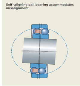
 When are self -aligning ball bearings and self aligning roller bearings used in centrifugal pumps?

For heavy loads, high speeds, and long bearing spans with no end thrust, self-aligning ball bearings  can well be adopted for line bearings on centrifugal pumps. The double row of balls runs in fixed grooves in the inner or shaft race, and the outer race is spherically ground (Fig-1); Therefore it operates as a pivot to take slight vibration or shaft deflection. It has very little thrust load (axial load) capacity and hence is not used for combined radial and thrust load in centrifugal pumps. With large shafts, the self- aligning spherical roller design is used instead of self- aligning ball bearings.

Self-aligning spherical roller bearings (Fig-2) can carry a combined radial and axial load with considerable thrust load component.


Fig-1.Self-aligning ball bearings
Fig-2.Self-aligning spherical roller brg.